
The 4-Arms Case
By now you should have a good idea of the techniques we shell take in order to discover the topological structure of the 4-Arms Machine's configuration space. We will start by examining the configuration space of the 3-Arms machine while an additional arm is restricting its motion. Next, we will find the nature of this restricted area by examining its borders. We already know the configuration space of the 3-arms machine is a sphere. By adding another arm to the 3-arms machine, the movement is restricted to a certain region of the sphere. Most of the states in this region, represent 2 positions of the newly placed arm (states in which no arm is stretched). Therefore, we must consider 2 copies of the restricted region. Just as in the previous case, the border of the restricted region represents all states in which the new arm is stretched. Since these states are represented in both regions they must be identified, the identification is achieved by connecting the borders of these regions. We will find out the nature of the restricted region by queering its border in the next applet:
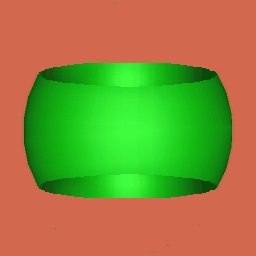
The restricted area on the sphere
Animation of the two restricted regions become one connected region: The Torus.
All the reasoning which were introduced above were not concrete, we know for a fact that the configuration space of the 4-arms machine is a torus but we have little clue as to how things really work out; We do not know how specific movements of the machine map to the configuration space. One of the main reasons for this lack of concrete is the fact that all the reasons we have introduced had only a topological nature. For instance we described the borders of the restricted region as topologically equivalent to 2 circles. Just as we have seen various maps of earth, in our case as well there are also various possible maps. However, it is possible to introduce a more concrete representation, which will also help us in future discussions. In the first page of this lesson, we mentioned that configuration space of our machines is made of disks somehow connected. A disk represents the movement of the machine while no arm can switch bends. It is more convenient to represent this restricted movement by a polygon and in our case a square as in the following applet:
Each edge in the above square represents states, in which the corresponding arm is stretched and each vertex represents a state in which two adjacent arms are stretched. Each square represents all states in which no arm can change its bends. Since each arm can take 2 possible bending, consequently there are 24 = 16 basic squares which constitute the configuration space. In the following applet, you can learn how these 16 squares are connected to form the configuration space of the 4-arms machine.
![]()